Voordat je gaat bouwen, stuur Peter dan eens een mailtje met je ontwerp. Hij kan vast commentaar geven. Het is een aardige kerel die je graag helpt.
Leon
Dat heb ik dus gedaan, en inderdaad antwoord gekregen.
Onderstaand een kleine samenvatting van de mail-wisseling:
***
1st question by Ron:
Importance of a straight (un-swept) ¼ chord line.
If I understand correctly you claim that one of the reasons why a straight ¼ chord line is a good idea is because it puts the lift forces of the outer wing areas at a low (actually zero) moment arm relative to the centre of gravity (CoG). The low Re associated with the small tip chord are likely to cause wandering of the lift force to a deeper part of the cord, causing a negative pitching moment. I understand that the wing tip panel with it’s low Re will show this behaviour, but I don’t understand how placing it’s centre of pressure in the CoG helps?
I mean, if the lift force at the tip panel moves 20mm aft, the resulting disturbance in pitch moment equilibrium will be Flift_tip * 20mm, regardless the original distance of lift force to the CoG. I also read somewhere that if the quantity (not the position) of Flift_tip changes due to low Re effects (or aileron differential), a position close to the wing’s CoG means this force disturbance causes a smaller pitching moment disturbance. But doesn’t it – by the same reasoning – also mean that the control authority of the ailerons on the pitching moment decreases just as much?
It seems that choosing a straight ¼ chord line is like ‘buying’ a lower sensitivity to disturbance forces from the tips but paying for it with less effective pitch control!? Is this a good deal in the end? Am I missing something here?
Answer by Peter: I am not quite sure weather I understand your question right, but you have to take into account, that a forward swept wing allows more taper ratio than a swept back wing for the same stall behaviour, so it is actually possible to have a smaller area (F) where the difficulties occur. On the other hand a swept back wing will have wider tip chord and thereby may not have these difficulties with Re in this order.
There also some other reasons for the straight ¼ line….it reduces torsional loads of the wing and most important I guess, it gives a longer lever arm to the fin, without having a fuse.
2nd Question by Ron: Importance of a low moment of inertia around the pitch axis.
You claim that one should strive (for a fast and dynamic plank, e.g. F3F) for a low moment of inertia around the pitch axis (light fin, short nose, ballast at CoG). I understand that this means less control-moment is required to accelerate the plane around the pitch axis, so smaller flap deflection are required and thus less un-cambering of the wing. But it the pitch- sensitivity of the wing to disturbance forces will be equally increased, possibly causing the dreaded rodeo ride.
I would think that the advantage of the small flap deflection is only present during the pitch-acceleration of the wing, so only a very small amount of time.
Answer Peter: Yes You are right about this, but that is precisely the point….during sharp turns, it seemed to me, that the plane with the lower inertia (short nose) was able to turn more tight than the model with the long nose. I made actually some test…you have may seen the picture of the green monster (Kaltenkirchen), with the very short nose, filled with lead. I flew the same model also with longer noses, to test this hypothesis. It is even so that some math calcs, do not show this difference, as it seems that the plane should be reacting fast enough almost regardless of the length of the nose…but in practice there is ! It seems to be a highly dynamic effect.
Q Ron: As soon as the wing has reached the desired rotation speed around the pitch-axis the flaps can return to the position that is dictated by the lift required for the turn radius and the static margin of the trim. This would mean a wing with low pitch inertia only has a small advantage during the initiation of the turn, but is always paying for this with ‘twitchiness’ around the pitch axis. Before reading your articles I was actually planning on really increasing the pitch moment inertia as much as practically possible to make it less nervous, but now I’m confused...
A Peter: Right….but turns are just a short period action….it is not even sure weather the flow over the airfoil can be calc. accurately in fx Xfoil
Remark Ron:
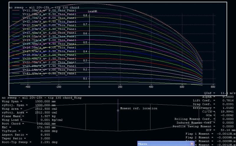
Anyway, given my restrictions on total mass and size I have decided to go for a 1500mm wing span with an aspect ratio of 9 that can be ballasted between 40 and 120 gram/dm2.
Reply Peter: Sounds reasonable…maybe you can get more out of the plane by moving the aspect ratio to 10 and using the thinned, lesser cambered PW51 or similar at the tip (made for lower re) together with the forward sweep design…..check the stall characteristics.
3rd question Ron:
Also, I am very curious about the status of project Amokka and it’s possible successor, a full-size F3F plank. I haven’t found any threads after you’re maiden in October 2008.
Answer Peter:
Well you may have seen the ETTO video on Vimeo…..a very nice plane
In the mean time things got a little bit slow with the bigger Amokka…but now the wing moulds are finished and I will build a wing very soon….the fuse is in the CAD work and will have a CG moving device….to even more improve the turn abilities of planks
Good luck with your plank…it seems a very fun project…..
")
…let me hear about it.
Inhoud van een 2e mail-ronde:
Remark Ron:I'll keep the 1/4 chords on a straight line; no sweep no dihedral, makes it easier to build the spar too.
Comment Peter:a dihedral of 1 degree is quite benefical.....
4th Question Ron:
Why does a forward sweep allow for a higher wing taper for the same stall behavior? Has it something to do with sweep creating a span-wise flow -> reducing the angle of attack -> reducing the amount of lift? Does XFLR take this effect into account?
Reply Peter:The induced angle of attack at the tip is less on a swept forward wing than on a straight one. With swept back wings it is the opposite. Just look at swept back flying wings with 2o degrees og more sweep. They usually have almost no taper and twist to have a safe stall. And yes also when the stall comes, then the span wise flow is directed inwards by a swept forward wing. Yes XFLR takes this into account...just try some extreme shapes.
5th question Ron:
Should I change the tip airfols a little? Do you mean for exampe take PW51 and reduce camber to 0,5% and thickness to 8%? If a little afraid I am causing more harm then good if I start messing about wit the airfoil. That said; aileron chord goes to zero towards the tip, so that should push the tips to higher lift when flying slow when compared to the section with up-deflected aileron. If I remove camber and decrease thickness, I guess I reduce operating Cl when flying slow but ALSO reduce max. possible Cl ?! And what happens at high speed, will I get tips creating downforce because the zero-lift angle of attack is different from the rest of the wing? Or am I over-thinking this?
Reply Peter:
I can ajust the airfoils for you if you want...no big deal. You can also make the chord of the flap deeper at the tip...this will give some twist at lower speeds...you can also simulate that in XFLR.
Inderdaad een hele aardige kerel, heel behulpzaam ondanks zijn beperkte vrije tijd.
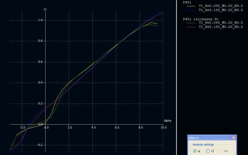
Ik heb gekeken of het zin heeft het PW-51 profiel voor de tips iets dunner te maken en/of minder welving te geven, zodat ze mindre kritisch zijn bij lage Re-getallen (minder kans op tip-stall bij langzaam vliegen).
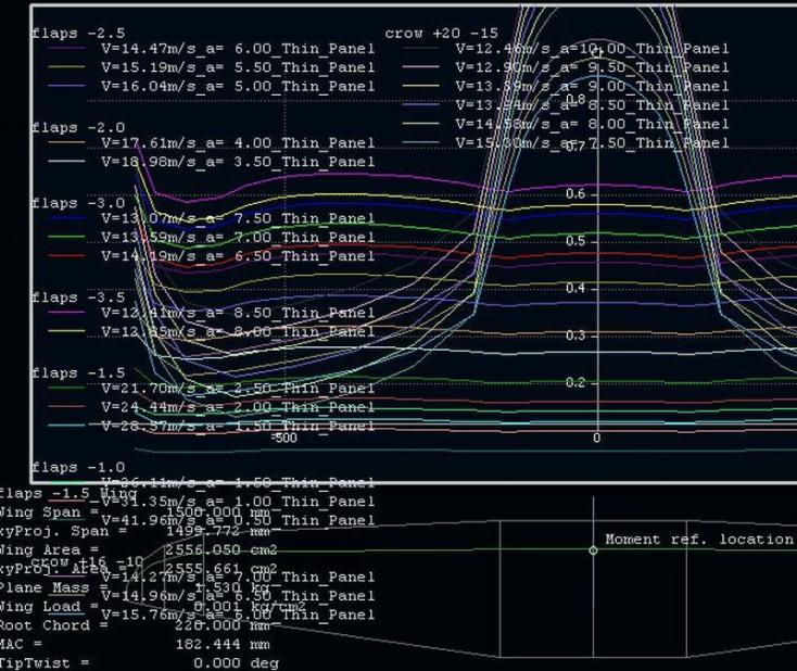
Zie onder Cl vs alpha bij Re-50k en 150k, voor het standaard profiel en één waarvan de dikte is verkleind van 8,9% tot 8%:
Ik zien nauwlijks verschil tussen de gele en groene lijn. Het dunnere profiel kan bij lage Re net zo veel invalshoek aan als het dikkere profiel. Ik zie dus geen reden de dikte te verkleinen.
Het verkleinen van de welving van 1,4 naar 0,5% verlaagde alleen maar de Cl, het vergrootte niet de maximaal toelaatbare invalshoek. Dat lijkt me dus ook niet zinvol.
Ik hou het dus maar gewoon bij een PW51 profiel van wortel tot tip.
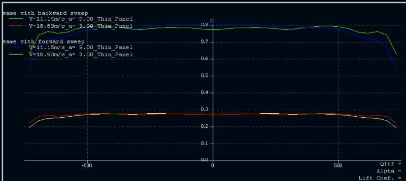
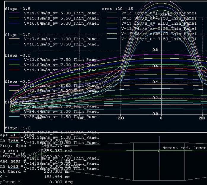
Het effect van pijlstelling op Cl-verdeling heb ik ook geprobeerd in XFLR:
De grafiek toont Cl vs span, bij invalshoeken 3 en 9 graden, voor een vleugel met 6 graden voorwaarte pijlstelling en 10 graden achterwaartse pijlstelling (gelijk oppervlak, profiel en vleugelbelasting). Bij de voorwaartse pijlstelling werken de tippen op een lagere Cl (blauwe en gele lijn). Waarom je 'dus' een kleiner tip-oppervlak mag gebruiken snap ik niet. Ik zou eerder denken dat je die lage Cl aan de tip moet compenseren met een GROTER tip-oppervlak om toch weer die felbegeerde elliptische liftverdeling te verkrijgen !?
M'n Bijbel (Martin Simons) weer eens herlezen.
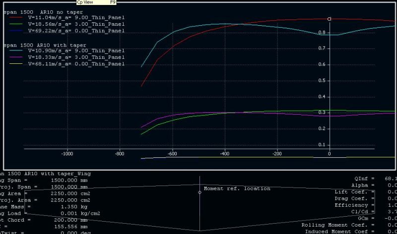
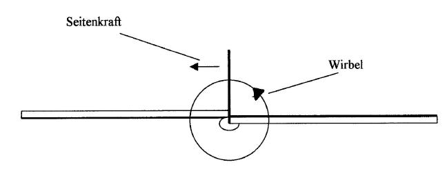
De tipwervel verkleind de invalshoek van de tips. Hoe langzamer je vliegt en hoe breder de tip hoe sterker dit effect. Een rechte vleugel (constante koorde) heeft dus een enorme tp-wervel maar is wel heel stall-safe (kleine Cl aan de tip).
Een tapse vleugel (bv wortel 200mm en tip 100mm, span 1500mm) heeft een minder sterke wervel en dus werken de tips bij een hogere Cl. Zie plaatje onder, Cl vs span, rechte en tapse vleugel, invalshoeken 3 en 9 graden:
(tapse vleugel is blauw en paars).
Ik begrijp alleen niet waarom de Cl van die tapse vleugel richting de wortel KLEINER wordt!?
Simons zegt daar 'te veel oppervlak' zit voor de lift die er gedragen moet worden, en dat daarom de Cl daar inzakt. Maar de lokale Cl wordt toch gewoon bepaald door de lokale invalshoek, waarom wordt die invalshoek kleiner bij de wortel?
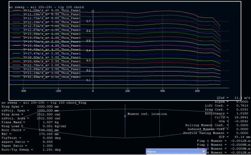
Ik begrijp het niet helemaal, maar ik heb besloten de koorde op 625mm vanuit het midden te verkleinen van 140 naar 130mm. Hierdoor wordt de liftverdeling iets beter elliptisch, Cl verdeling ziet er volgens mij ook wel OK uit. Ik heb het gevoel dat hier niet meer zo héél veel aan te verbeteren valt, in elk geval niet door mij.
Huidige status, Cl vs span (redelijk gelijkmatig, iets afvallend aan de tips):
en lift vs span (nagenoeg elliptisch):
Dirk, bedankt voor de link naar het draadje op RCN. De F3F plank van Stefan Siemens lijkt me een mooi project, al lijkt hij zelf een beetje teleurgesteld te zijn in de prestaties.
Ik moet je adviezen wat betreft Nurflugel en 0-invalshoek nog even op me laten inwerken.
Ik denk (?) dat ik per definitie bij hoge snelheid over tegelijk Cl=0 krijg zolang ik overal hetzelfde profiel gebruik. Toch? Ik vraag geen hoge prestaties bij lage snelheid, zolang het ding maar veilig te landen is. Ik ben bang dat ik met dat gepruts en gedraai aan die profielen hoogsten een klein beetje kan winnen op lage snelheid met het risico vele te verliezen op hoge snelheid. Ik begrijp het eigenlijk nog niet goed genoeg, en ik wordt een beetje ongeduldig.
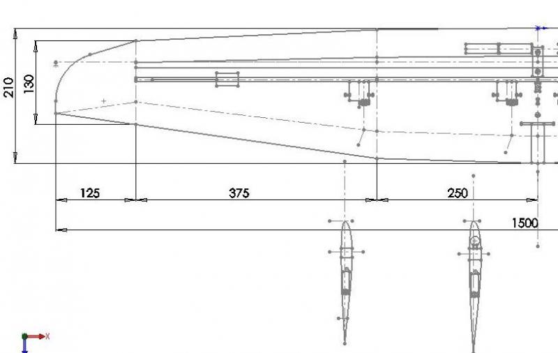
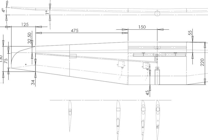
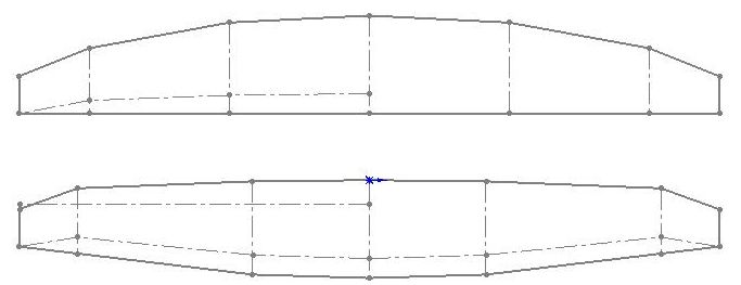
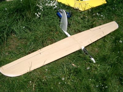
Onderstaand de layout van de halve vleugel:
Het plan is om de ontvanger en de accu in de vleugel te doen, zodat de romp simpel en slank kan zijn.
- 4 AA eneloops in het midden, net voor de ligger.
- Ligger op 25% van de koorde, recht (geen pijlstelling). Waarschijnlijk toch maar 1 graadje v-stelling, op aanraden van Peter Wick.
- ontvanger zover richting tip als dikte toelaat. Vanaf daar dus geen carbon in de vleugel. Ontvanger wordt de Multiplex RX5 M-link 2,4GHz
- 4 servo's Futaba S3150, met RDS systeem. Uitslagen ca. +/- 20 graden maximaal.
- ballast komt niet-verwijderbaar in de romp. Ballast veranderen = andere romp monteren.


")


 . Hoeft geen probleem te zijn bij gebruik van goed centrerende en nauwkeurige servos en spelingvrije linkage. (absolute must bij planks zoals je vast al weet)